2023年5月22日星期一

How to ultra dicing wafer with diamond dicing blade?

 afers are the basic raw materials for the production of semiconductor devices. High-purity semiconductor materials are made into wafers through processes such as crystal pulling and slicing. Wafers produce tiny control circuit structures through a series of semiconductor manufacturing processes, and then through dicing , packaging, and testing become chips, which are widely used in various electronic instruments.

Wafer chamfering and edge chamfering are usually made of curved dicing or internal dicing saw blades. The outer edges of the dicing wafers are particularly sharp. In order to prevent the cracking of the corners from affecting the hardness of the wafer, or damaging the surface finish and subsequent processes bringing environmental pollution, it is necessary to automatically correct the edge, shape and outer diameter of the wafer with special numerical control equipment, so the dicing knife directly affects the quality of the finished product.

Moresuperhard can provide wafer edge chamfering grinding wheel, electroplated diamond band saw blade, wafer back grinding wheel,diamond dicing blade,cylindrical diamond grinding wheel for silicon ingot.

How to dicing wafer?

Semiconductor wafer dicing machine

The semiconductor wafer dicing machine divides the wafer containing many chips into wafer particles. The quality and efficiency of dicing directly affect the quality and production cost of chips. Semiconductor wafer dicing machine mainly includes grinding wheel dicing machine and laser dicing machine. Grinding wheel dicing machine is a precision numerical control equipment that integrates technologies such as water, gas, electricity, air static pressure high-speed spindle, precision mechanical transmission, sensors and automatic control. It is characterized by low dicing cost and high efficiency, and is suitable for dicing thicker wafers.

Laser Scribing Machine

The laser scribing machine uses a high-energy laser beam to irradiate the surface of the workpiece, so that the irradiated area is partially melted and vaporized, so as to achieve the purpose of scribing. It is characterized by high dicing precision and fast dicing speed, and is suitable for dicing thinner wafers.

Semiconductor wafer dicing machine laser dicing machine

Dicing/scribing process

Scribing blade dicing methods include one-time dicing and step-by-step continuous dicing. High efficiency, low cost and long service life. It is the most widely used dicing process and has advantages on thicker wafers (>100 microns).

Laser dicing has high precision and high speed. It is mainly suitable for dicing thinner wafers. Diamond dicing is the mainstream dicing technology. dicing uses a blade composed of diamond particles and a binder. During the dicing process, diamond particles are fixed on the tool body with metal nickel as abrasive particles. The blade rotates and feeds at a certain speed, and uses water as the dicing fluid. During the dicing process, the diamond particles expand and form structures called "chip pockets" with the binder, scooping up the dicing channel material and then separating it. During the dicing process, the diamond particles are constantly worn away, exposing new particles, keeping the blade sharp and removing dicing debris. The debris generated during the dicing process will adhere to the blade, so try to prevent the dicing debris from adhering during the dicing process, and properly handle the dicing debris to ensure the normal operation of the blade during the dicing process.

For diamond dicing saw blade, the larger the diamond particles, the stronger the cutting ability of the blade, the slower the wear of the diamond particles, and the longer the service life of the blade. However, the larger the particle size, the greater the impact of the cutting process on the cutting surface, which is likely to cause serious defects such as cracks and chipping. Smaller diamond grits reduce the impact on the cutting surface during cutting and reduce the risk of larger cutting defects. However, if the diamond cannot be shed and renewed in time, it is easy to wrap the cutter, resulting in a sharp decline in the cutting ability of the blade and serious defects.

The diamond particle concentration of the dicing blade body will significantly affect the quality of cutting chips. When the concentration of diamond particles is large, the diamond particles will fall off and be renewed in time with the wear of the binder, which is beneficial to prolong the service life of the blade. Also, the softer the binder, the easier it is for the diamonds to come off, and vice versa. Therefore, cutting with a harder bond can severely damage the cut surface, while a softer bond has less impact and less damage. The choice of diamond particle size and concentration should be combined with the type of binder and should be considered comprehensively.

IMG_1114.jpgIMG_1095.jpg

Dicing process

The chip is cut into individual particles by the wafer, and then it is ready to use after being packaged by the chip. When scribing, the moving speed of the scribing knife and the rotation speed of the scribing knife should be controlled. The thickness of different chips and the viscosity of the blue film need to have corresponding matching parameters to reduce debris during the scribing process. Residual silicon dross from the cutting process can damage cutting tools and swarf, resulting in yield loss. During the cutting process, it needs to be washed with clean water to remove silicon slag, and the spray angle and water volume should be controlled.

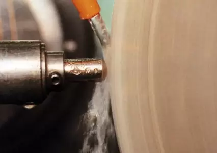
Diamond saw blades dicing wafer blocks at a high speed of 30,000-40,000 revolutions per minute. At the same time, the workbench carrying the wafer moves linearly at a certain speed along the tangent direction of the contact point between the blade and the wafer, and the silicon wafers produced by cutting the wafer are washed away by the separator water. To achieve exceptional chip surface protection during scribing, some chips need to be cut twice in all cuts. At this time, the blade used for the first cut is relatively wide, and the blade used for the second cut is relatively narrow.

dicing wafer process

Factors Affecting Cut Quality

There are many factors that affect the quality of wafer cutting, including materials, cutting instruments, working environment, cutting methods and other factors. From a material point of view, the silicon substrate and circuit layer materials of the silicon wafer will lead to different mechanical properties during the silicon wafer cutting process. The choice of blades of different materials will have different requirements for the cutting method, and therefore will show different cutting qualities. From the point of view of cutting instruments, since the cutting power of different machines is different, the choice of cutting table will also affect the cutting quality. From the perspective of working environment, the pressure and flow of cooling water are the factors that affect the cutting quality. If the water flow speed is too slow, the cooling effect will be insufficient, and the heat generated by cutting friction will be difficult to discharge and accumulate in time, which may cause the diamond abrasive grains to break, reduce the cutting ability and cutting accuracy of the blade, and affect the cutting of the blade because the cutting debris cannot be removed in time ability. From the perspective of cutting method, it mainly involves cutting depth, blade speed and feed speed. Proper parameters are very important to obtain good cutting quality. Other factors, such as machine operator skill, also affect wafer cut quality.

Dicing defect

The types of defects that are prone to occur in wafer dicing mainly include cracks, chipping and peeling. These defects may cause direct damage to the chip, and may also affect the subsequent packaging and subsequent use reliability of the chip. For example, microcracks generated by dicing will introduce stress into the chip and become a potential chip fragile area, affecting the reliability after packaging. During the cutting process, the chip is impacted by the powerful cutter body, and the metal layer and silicon substrate are peeled off. If the edge collapse is too large, the functional area of the chip will be damaged, which will directly lead to chip failure. The delamination of the metal layer caused by the impact during the cutting process, although the silicon substrate is not damaged, usually does not cause functional damage to the chip, but if the peeling area is large and extends to the functional area, it is also very dangerous.

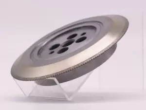
The production of wafer dicing blade is first roughed by carbide tools, then semi-finished by PCD blades, and finally finished by single crystal diamond turning tools to achieve extremely high dimensional accuracy and surface finish. 

Moresuperhard single crystal turning tool finishes the surface and inner hole of the wafer dicing blade, and the dicing performance is more stable, thereby improving the cutting quality and cutting accuracy of the substrate after the dicing knife is packaged, and greatly increasing the production capacity. It is tailored for users to meet the needs of customers. Its craft and project needs.

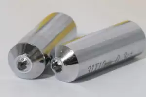
Cutting tools for turning diamond dicing blade

Single crystal cutting tools have many advantages in ultra-precision machining. High hardness and wear resistance can minimize the impact of tool tip wear on workpiece size during ultra-precision machining. In addition, good thermal conductivity and low thermal expansion coefficient can prevent large thermal deformation during cutting. Moreover, the surface roughness of the single crystal tool is small, the cutting edge is very sharp, up to Ra0.01-0.006μm, and the single crystal cutting allowance is less than 0.02mm.

turninng diamond disco baldesingle crystal diamond cutting tools


Single crystal machinable materials and applicable industries are as follows:

Metal materials: aluminum alloy, aluminum, brass, copper, gold, nickel, silver, tin, zinc, HRC50 hard steel, etc.

Polymer materials: acrylic resin, nylon, polypropylene, polystyrene, silicone, etc.

Infrared crystal materials: calcium fluoride, gallium arsenide, germanium, magnesium fluoride, silicon, zinc selenide, zinc sulfide, etc.

Military industry: off-axis three-mirror, missile fairing, sophisticated infrared optical system, etc.;

Civilian use: spherical, aspheric free-form surface lens, Fresnel lens, high-precision mold core, super-bright and super-uniform light guide plate, compound eye structure, etc.

How to grind 316 stainless steel?

 Stainless steel is widely used because of its good corrosion resistance, but there are many types of stainless steel, 3 series, 4 series, 6 series, each series will be subdivided according to the added elements, 304, 316, 420, 660, etc...

316 stainless steel, also known as A4 stainless steel, contains 16% chromium, 10% nickel, and 2-3% molybdenum. The material elements can resist chloride corrosion, so it’s more corrosion-resistant and heat-resistant than 304, and it’s relatively less easy to process.

In terms of grinding, the following grinding difficulties can be sorted out:

■ Easy to cause grinding heat

Stainless steel has large plastic deformation and low thermal conductivity. Under the high-speed friction, it’s easy to increase the grinding temperature, cause surface burns, and reduce processing accuracy.

■ Abrasive is easy to blocked

Stainless steel is tough, and the chips are sticky and sheet, which are easy to stick to the surface of the grinding wheel. When the surface of the grinding wheel is blocked, the cutting force will decrease, lead to the temperature rise.

■ High frequency of dressing

As mentioned above, stainless steel chips are viscous and will cause sticking. In order to keep the cutting force , the grinding wheel needs to be dressed frequently, which will increase the processing cost and reduce the efficiency.

In order to solve the above problems, we must start with the grinding wheel used. If the abrasive is easy to blocked, the selection of the grinding wheel can follow these points for reference:

■ High heat dissipation

The grinding wheel mainly relies on pore to dissipate heat. The heat dissipation and chip removal of the grinding wheel are determined by the distribution and size of the pores. The grinding wheel with evenly distributed pores dissipates heat evenly and can greatly reduce the grinding heat. The effect of improving the surface precision can be achieved after the temperature is lowered.

■ High strength bond

The strength of the bond determines grinding wheel’s life and cutting force. The harder the grinding wheel, the better the life. However, if it’s too hard, the abrasive will not fall off normally, which will affect the cutting force. If it’s too soft, the abrasive will fall off frequently, and the sand will scratch the work piece. So how to adjust the hardness of the grinding wheel to suit your grinding method and work piece is important.■ Choose abrasives with high cutting force

Abrasives with high cutting force are important for grinding stainless steel. Because stainless steels are tough, they require greater cutting force for complete removal. Most recommend GC abrasives for grinding. They have high hardness and brittleness and can be sharpened by self-sharpening. As abrasive fall off, it takes away the heat and keep stable and sharp.

In summary, because 316 stainless steel has high toughness, high wear resistance and corrosion resistance, it is easy to cause sticking, blocking and grinding heat for grinding. The solution is to choose abrasives with high self-sharpening and high cutting force, and the most important design of pore as a strong backing for abrasives. Shengyao carefully selected a special grinding wheel with large pore for the above characteristics, [PTII dimensional gas grinding wheel, which has all the above characteristics, and the quality of grinding wheel is stable. At the same time, it has strong heat dissipation and cutting force, and has both surface roughness and cutting characteristics. I hope the above information can solve your problems.

Why does grinding stainless steel scratch easily?

(1) The size of the abrasive grains of the grinding wheel is uneven 

The largest and smallest abrasive grains in the grinding wheel may have several times the difference in grain size, and the larger abrasive grains are more prominent, which will cause uneven depth of the ground workpiece.

(2) Grinding heat causes excessive cutting and debris sticking

Stainless steel with a softer texture is prone to thermal expansion due to grinding, and the amount of cutting is relatively large, resulting in deep grooves on the workpiece. The high temperature will also melt the debris and adhere to the surface of the grinding wheel or workpiece, which will easily cause scratches during grinding.

(3) Scratched by debris from abrasive particles

 If the bonding force of the grinding wheel is uneven, a large piece of sand may fall off during the grinding process. If it is not removed quickly and it stays on the surface of the workpiece or the grinding wheel, it will form serious scratches.

When grinding stainless steel, white fused alumina(WA) is generally used. White corundum grinding wheel has good cutting performance and good self-sharpening. When grinding acid- resistant stainless steel, grinding scratches can be reduced. Especially monocrystalline fused alumina with large aperture has good application effect in production.

Because CBN has high hardness, grains easily wear, and good chemical stability, and it does not have a chemical affinity with iron group elements, therefore CBN grinding wheels are not blocked easily when grinding. Grinding stainless steel with CBN grinding wheel has the best effect.

 metal CBN grinding wheel resin CBN grinding wheel

The solution to the difficult machining of stainless steel

 Stainless steel material, as the name suggests, is a steel material that is not easy to rust. Ferritic stainless steel is the most common type of stainless steel material, and it is a stainless steel with ferrite structure as the main structure in use. The chromium content of this stainless steel is between 11% and 30%. In addition, it also contains a small amount of molybdenum, titanium, niobium and other elements.

The difficulty of stainless steel processing is mainly reflected in these aspects:

1. Cutting tool material selection

Due to the high cutting force and high cutting temperature of stainless steel parts, cubic hydrogenated turning inserts with hardness second only to diamond and high temperature resistance can be used. In addition, its chemical inertia is very large, and iron group metals have no chemical action at 1200~1300 °C, which is very suitable for processing stainless steel materials.

2. When sharpening the rake face, the roughness value should be small

In order to avoid chip jamming, the front and rear surfaces of the tool should be carefully ground to ensure a small roughness value, thereby reducing chip flow resistance and avoiding chip jamming.

3. Keep the cutting tool edge sharp

The cutting edge of the knife should be kept sharp to reduce work hardening. The infeed and reverse infeed should not be too small, so as not to cut the tool in the hardened layer and affect the service life of the tool.

4. Cutting tool geometric parameters

The geometrical parameters of the tool have an important influence on its cutting performance. In order to make the cutting of cemented carbide tools light and smooth, a larger rake angle should be used to improve tool life. This is conducive to strengthening the cutting edge and giving full play to the advantages of the high compressive strength of ceramic tools. The size of the relief angle directly affects the wear and edge strength of the tool. The change of the entering angle will affect the change of radial cutting force and axial cutting force, as well as the change of cutting width and cutting thickness.

5. Pay attention to the grinding of the chip breaker

Due to the strong toughness of stainless steel chips, the chip flute on the rake face of the tool should be properly ground to facilitate chip breaking, chip holding and chip removal during the cutting process.

6. Choose the right cutting oil

Since stainless steel is prone to cohesion and poor heat dissipation, it is very important to choose a cutting oil with good anti-cohesion and heat dissipation during the cutting process, such as Yida Borun special stainless steel cutting oil, which has good cooling, cleaning, Anti-rust and lubricious.

7. Selection of cutting parameters

According to the characteristics of stainless steel materials, low speed and high feed should be selected when cutting. Using the above-mentioned process can overcome the difficulty of stainless steel processing, greatly improve the tool life of stainless steel in the cutting process, reduce the number of tool replacements in operation, and achieve satisfactory results in improving production efficiency and cutting accuracy, reducing cloth, etc. Labor intensity and overall production cost.

Stainless steel parts processing technology

Through the analysis of the above processing difficulties, the processing technology of stainless steel and the design of related tool parameters should be quite different from those of ordinary structural steel materials. The specific processing technology is as follows:

1. Drilling

During drilling, due to the poor thermal conductivity and small elastic modulus of stainless steel, it is difficult to process holes. To solve the problem of hole processing of such materials, it is mainly to select the appropriate tool material, determine the reasonable geometric parameters of the tool and the cutting amount of the tool. When drilling the above materials, the drill bits should generally be made of W6Mo5Cr4V2AI, W2Mo9Cr4Co8 and other materials. However, when the commonly used W18Cr4V ordinary standard high-speed steel drill bit is used for drilling, due to the shortcomings of small apex angle, too wide chips, it cannot be discharged out of the hole in time, and the cutting fluid cannot cool the drill bit in time, and the stainless steel material has poor thermal conductivity, resulting in concentration. When the cutting temperature on the cutting edge rises, it is easy to cause burns and chipping of the two flanks and the main edge, which reduces the service life of the drill bit.

1) Tool geometric parameter design When drilling with W18CrV junction, the cutting force and cutting temperature are concentrated on the drill tip. In order to improve the durability of the cutting part of the drill bit, the apex angle can be appropriately increased. The apex angle is generally selected as 135° ~140. The increase of the apex angle will also reduce the rake angle of the outer edge and narrow the cuttings to facilitate chip removal. However, after increasing the apex angle, the chisel edge of the drill bit becomes wider, resulting in an increase in cutting resistance. Therefore, the chisel edge of the drill bit must be ground. After grinding, the bevel angle of the chisel edge is 47~55°, and the chisel edge rake angle is 3° ~5°, when grinding the chisel edge, the corner between the cutting edge and the cylindrical surface should be ground into rounded corners to increase the strength of the chisel edge. Due to the small elastic modulus of the stainless steel material, the elastic recovery of the metal under the chip layer is large, and the work hardening is serious during the processing. If the relief angle is too small, the wear of the flank of the drill bit will be accelerated, and the cutting temperature will be increased, which will reduce the life of the drill bit. Therefore, the relief angle must be increased appropriately, but if the relief angle is too large, the main edge of the drill will become thinner and reduce the rigidity of the main edge, so the relief angle should be 12° ~ 15°. In order to narrow the drill chips and facilitate chip removal, it is also necessary to open staggered chip splitters on the two flanks of the drill bit.

2) Cutting amount selection When drilling, the choice of cutting amount should start from the basic point of reducing the cutting temperature, because high-speed cutting will increase the cutting temperature, and high cutting temperature will aggravate tool wear, so the cutting amount is the most important is the choice of cutting speed. Generally, the cutting speed is 12 ~ 15m/min more appropriate. The feed rate has little effect on the tool life, but if the feed rate is too small, the tool will cut in the hardened layer and aggravate the wear; if the feed rate is too large, the surface roughness will be deteriorated. Combining the above two factors, it is advisable to choose the feed rate as 0.32 ~ 0.50mm/r.

2. Reaming processing

1) Tool geometric parameter design Most of the reaming of stainless steel materials use carbide reamers. The structure and geometric parameters of reamers are different from ordinary reamers. In order to enhance the strength of the cutter teeth and prevent chip clogging during reaming, the number of reamer teeth is generally relatively small. The rake angle of the reamer is generally 8° ~ 12°, but in some specific cases, in order to achieve high-speed reaming, the rake angle of 0° ~ 5° can also be used; the back angle is generally 8° ~ 12°; the main declination angle The choice of the hole varies depending on the hole. Generally, the through hole is 15° ~ 30°, and the non-through hole is 45°; when reaming, in order to make the chips discharge forward, the blade inclination angle can also be increased appropriately, and the blade inclination angle - - generally 10° ~ 20°; the margin width is 0.1 ~ 0.15mm; the upper inverted cone of the reamer should be larger than the ordinary reamer, the carbide reamer is generally 0.25 ~ 0.5mm/100mm, and the high speed steel reamer is 0.1 ~ 0.25mm/100mm; the length of the corrected part of the reamer is generally 65% ~ 80% of the ordinary reamer, and the length of the cylindrical part is 40% ~ 50% of the ordinary reamer.

2) The cutting amount is selected when reaming, the feed rate is 0.08 ~ 0.4mm/r, the cutting speed is 10 ~ 20m/min, the rough reaming allowance is generally 0.2 ~ 0.3mm, and the fine reaming allowance is 0.1 ~ 0.2mm. Carbide cutters should be used for rough reaming, and high-speed steel cutters can be used for fine reaming.

3) When the cutting fluid is made of stainless steel for reaming, the total loss system oil or molybdenum disulfide can be used as the cooling medium.

3. Boring processing

1) Tool material selection Due to the high cutting force and high cutting temperature when processing stainless steel parts, the tool material should try to choose YW or YG cemented carbide with high strength and good thermal conductivity. YT14 and YT15 carbide inserts can also be used for finishing. When processing parts of the above materials in batches, ceramic material cutting tools can be used. Since the main characteristics of this type of material are high toughness and severe work hardening, the chips for cutting these materials are generated in the form of unit chips, which will cause the tool to vibrate and easily cause the blade to be micro. Therefore, the first thing to consider when choosing ceramic tools to cut parts of such materials is microscopic toughness. At present, Sialon is a better choice, especially the a/β Sialon material, which attracts attention because of its excellent high-temperature deformation resistance and diffusion wear performance, and has been successfully applied to cutting nickel-based alloys, and its service life is far More than Al2O3 based ceramics. In addition, SiC whisker-reinforced ceramics are also a very effective tool material for cutting stainless steel or nickel-based alloys.

For the processing of quenched parts of such materials, CBN (cubic boron nitride) blades can be used. The hardness of CBN is second only to diamond, and the hardness can reach 7000 ~ 8000HV, so the wear resistance is very high. Compared with diamond, the outstanding advantages of CBN are: The heat resistance is much higher than that of diamond, up to 1200°C, and can withstand very high cutting temperatures. In addition, its chemical inertness is very large, and it has no chemical effect with iron group metals at 1200 ~ 1300 ° C, so it is very suitable for processing stainless steel materials. Its tool life is dozens of times that of cemented carbide or ceramic tools.

2) Tool geometric parameter design The tool geometric parameter plays an important role in its cutting performance. In order to make the cutting light and smooth, the carbide tool should adopt a larger rake angle to improve the tool life. Generally, the rake angle is 10°~20° for rough machining, 15°~20° for semi-finishing, and 20°~30° for finishing. The basis for selecting the main deflection angle is that when the rigidity of the process system is good, it can be 30°~45°; if the rigidity of the process system is poor, it can be 60~75°; when the ratio of the length to the diameter of the workpiece exceeds 10 times, it can be 90° °.

When boring stainless steel materials with ceramic tools, in most cases, ceramic tools are cut with a negative rake angle. Generally, the size of the front angle should be 5°, which is conducive to strengthening the knife work and giving full play to the superiority of the high compressive strength of ceramic tools. The size of the back angle directly affects the wear of the tool and also affects the strength of the knife. Generally, 5°~12 °. The change of the main deflection angle will affect the changes of the radial cutting force and axial cutting force, as well as the cutting width and cutting thickness. Because the vibration of the process system is extremely unfavorable to the ceramic tool, the choice of the main deflection angle should help reduce this vibration, and one should choose 30°-75°. When CBN is selected as the tool material, the geometric parameters of the tool are rake angle 0° ~ 10°, relief angle 120° ~ 20°, and entering angle 45° ~ 90°.

3) When sharpening the rake face, the roughness value should be small. In order to avoid the phenomenon of chips sticking to the knife, the front and flank faces of the tool should be sharpened carefully to ensure a small roughness value, thereby reducing the chip outflow resistance and avoiding chip sticky knife.

4) The cutting edge of the tool should be kept sharp. The cutting edge of the tool should be kept sharp to reduce work hardening. The feed rate and back cutting amount should not be too small to prevent the tool from cutting in the hardened layer and affect the service life of the tool.

5) Pay attention to the grinding of the chip breaker. Due to the strong and tough characteristics of stainless steel chips, the grinding of the chip breaker on the rake face of the J tool should be appropriate, so that chip breaking, chip containment, and chip removal are convenient during the cutting process.

6) The selection of cutting amount is based on the characteristics of stainless steel materials, and it is advisable to choose low speed and large feed rate for cutting during processing.

When using ceramic tools for boring, the reasonable selection of cutting amount is one of the keys to give full play to the performance of ceramic tools. For continuous cutting of ceramic tools, the cutting amount can be selected according to the relationship between wear durability and cutting amount; for intermittent cutting, the reasonable cutting amount should be determined according to the law of tool damage. Due to the superior heat resistance and wear resistance of ceramic knives, the impact of cutting amount on tool wear life is smaller than that of cemented carbide tools. In general, when machining with ceramic tools, the feed rate is most sensitive to the damage of the tool. Therefore, according to the nature of the workpiece material, on the premise that the power of the machine tool, the rigidity of the process system and the strength of the blade are allowed, when boring stainless steel parts, choose a high cutting speed, a large amount of back cutting and a relatively small cutting edge. Give the amount.

How to use surface grinder for form grinding?

 Principles of form grinding

The principle of form grinding is to decompose the outline of complex parts into several line segments and circular arcs, and then grind them segment by segment according to a certain process sequence to make the joints smooth and meet the design requirements of the product. Form grinding has the advantages of high precision and high efficiency, the grinding precision can reach IT5~IT6, the surface roughness is Ra0.4, and the lowest can reach Ra0.1. Form grinding often uses a form grinder or a surface grinder.

form grinding

Method of Form Grinding

There are many methods of form grinding, commonly used are form grinding wheel grinding method and form fixture grinding method. The forming grinding wheel grinding method is to use tools to trim the grinding wheel into the opposite profile that is completely consistent with the workpiece to be ground, and perform grinding to obtain the required forming surface; the forming fixture grinding method refers to placing the workpiece in the forming fixture On the other hand, the position of the workpiece is adjusted by using the fixture, so that the workpiece can be moved or rotated quantitatively during the grinding process, thereby obtaining the processing method of the desired shape. Commonly used fixtures include sinusoidal precision vise, sinusoidal magnetic table, sinusoidal centering fixture and universal fixture. The sinusoidal precision vise and the sinusoidal magnetic force table are mainly used for grinding planes or inclined surfaces. When the two are used together, they can grind complex-shaped forming surfaces composed of planes and arcs; the sinusoidal centering fixture is mainly used for grinding punches, cores, etc. Different arc surfaces, planes and equal grooves on the same axis; the universal fixture is a more perfect forming fixture developed from the sinusoidal centering fixture, which is used to grind arcs and inclined surfaces of multiple centers.

In production, there are two main methods for forming and grinding parts using a surface grinder. One is grinding with a shaped grinding wheel after dressing, and the other is grinding with a special fixture.

The contour accuracy of form grinding mainly depends on the contour accuracy of the dressed grinding wheel. The primary task of the form grinding wheel grinding method is to use the grinding wheel dressing tool to obtain the required profile. The commonly used grinding wheel dressing method uses a diamond pen mounted on the dressing fixture. Dressing, the used fixtures are grinding wheel angle dressing fixtures and grinding wheel arc dressing fixtures. Grinding wheel angle dressing fixture, when grinding the inclined surface of the workpiece, use the angle grinding wheel, the angle grinding wheel is a conical part trimmed by the flat grinding wheel, when dressing, the grinding wheel is driven by the grinding head, and the diamond pen on the angle dresser is relative to the axis of the grinding wheel Tilt at a certain angle and move back and forth to dress the grinding wheel until the required conical surface is repaired.

Grinding wheel angle dressing fixture

Although there are many structures of tools for trimming arc grinding wheels, their principles are the same. As shown in Figure 4, the grinding wheel arc trimming fixture is shown. The distance from the diamond tip to the center of rotation of the main shaft is the radius of the arc to be trimmed. This value is It is adjusted by placing a gauge block between the diamond tip and the reference surface. When dressing the grinding wheel, the value of the gauge block should be calculated according to the condition of the grinding wheel (convex or concave) and the radius, and adjusted by the gauge block. When the grinding wheel is rotating at a high speed, rotate the hand wheel to make the diamond pen swing back and forth around the center of the main shaft to trim the arc grinding wheel.

Grinding wheel angle dressing fixture

1. Although there are many structures of tools for trimming arc grinding wheels, their principles are the same. Grinding wheel arc trimming fixture is shown. The distance from the diamond tip to the center of rotation of the main shaft is the radius of the arc to be trimmed. This value is It is adjusted by placing a gauge block between the diamond tip and the reference surface. When dressing the grinding wheel, the value of the gauge block should be calculated according to the condition of the grinding wheel (convex or concave) and the radius, and adjusted by the gauge block. When the grinding wheel is rotating at a high speed, rotate the hand wheel to make the diamond pen swing back and forth around the center of the main shaft to trim the arc grinding wheel.

2. Use the forming grinding wheel to grind the punch, that is, trim the grinding wheel into a reverse surface that completely matches the workpiece surface, and then use the grinding wheel to grind the workpiece to obtain the desired shape. There are many ways to dress the grinding wheel, the main ones are as follows:

(1) When dressing the grinding wheel with diamond, most of the geometric shapes of the forming surface are trimmed in sections, but some of the grinding wheels are trimmed into shape. This method of dressing the grinding wheel is mainly done through various grinding wheel tools; Grinding wheel repairing tools in production mainly include angle repairing, arc grinding wheel repairing tools, universal grinding wheel repairing tools, profiling grinding wheel repairing tools, etc. Horizontal grinding wheel angle tool. It is mainly used to grind the forming grinding wheel with various angles between 0º and 90º, and then use this grinding wheel to grind the bevel of the workpiece. When dressing the grinding wheel, the position of the diamond tip is adjusted by calculating the pad value according to the convex or concave shape and radius of the grinding wheel to be repaired. The horizontal arc dressing grinding wheel fixture can dress various concave and convex arcs with different radii, or profiles connected by arcs and arcs. When trimming a non-arc surface, if the shape of the workpiece to be ground is complex or the contour is non-arc, special profiling tools can be used to trim the grinding wheel. The tool is a dedicated; profiling tool for profiling wheels that love to dress convex surfaces. The mold tool for trimming the concave forming grinding wheel is basically the same as the profiling tool for the convex forming grinding wheel, but the contact of the profiling template used should be pointed. When using the grinding wheel repairing tools introduced above, attention should be paid to the diamond tool holders used must be clamped and must not be loosened.

Single-Point-Diamond-dresser-for-Aluminum-oxide-grinding-wheel-on-surface-grinder.jpgrotary diamond dresser for dressing grinding wheel.jpg

When grinding the workpiece by using fixture grinding, the workpiece can be clamped on the special fixture according to certain conditions. During the processing process, the position is fixed or continuously changed for grinding to obtain the required shape. Commonly used grinding fixtures include: precision vise, sinusoidal magnetic force table, sinusoidal indexing fixture, universal fixture, rotating magnetic force table and center hole splint, etc. This grinding method is generally carried out on a surface grinder. In production, in order to ensure the quality and efficiency of grinding, the method of comprehensive use of shaped grinding wheels and fixtures is generally used, which can greatly reduce the manufacturing cost of parts.

Conversion of form grinding process dimensions During form grinding, the operator needs to convert the design dimensions of the pattern into the process dimensions of form grinding. The reason is that the size of process equipment parts is generally marked according to the design basis, but the construction basis used in form grinding is often inconsistent with the design basis. However, due to the different processing methods of individual parts, there are also different requirements for the size conversion of the forming grinding process.

How to choose dressing speed?

Why need dressing grinding wheels?

dressing

During the grinding process, the state of the grinding wheel will directly affect the grinding result. The state of the grinding wheel includes changes in the cutting force and shape of the grinding wheel. These changes will affect the yield and reproducibility of the ground product.

Moresuperhard can provide single point diamond dresser , diamond rotary roller dresser, conventional abrasive grinding wheel for dressing different kind of grinding wheel, any dressing method can inquiry us!

Single Point Diamond Dresser Rotary Diamond Dresser

What is the main reason for the loss of cutting force of the grinding wheel?

1. During the grinding and extrusion process of abrasive grains, the edges and corners are gradually rounded, which we call passivation. At this time, the self-sharpening ability of the grinding wheel does not play a role in time, which will reduce the cutting force and cannot effectively perform the grinding function.

2. Debris will be generated during the grinding process, especially for viscous materials. If the pores of the grinding wheel are not large enough or the porosity is low, debris will easily fill the pores and cause blockage. As a result, the grinding wheel becomes a non-serrated plane and loses cutting force.

dressing

During the use of the grinding wheel, wear and tear will occur. Such loss will cause the gradual loss of the roundness of the grinding wheel and the unevenness of the grinding surface of the grinding wheel. This situation will cause problems such as deflection during grinding and reduced grinding efficiency.

In these unstable states, the grinding wheel must be trimmed to restore the cutting force or true roundness of the grinding wheel. However, because the grinding wheel rotates at a high speed during processing, it is often impossible to directly observe whether the grinding wheel has lost its cutting force or is uneven from the naked eye. However, many grinding phenomena will occur when the cutting force is lost. If these phenomena occur, it can be estimated whether the grinding wheel needs to be dressed.

The insufficient cutting force caused by passivation and clogging, and unevenness caused by wear will be directly reflected on the grinding result; so when the following conditions occur during grinding, it is time to repair the grinding wheel.

How to choose dressing speed?

If the dressing speed is faster, the serrated part will be thicker, that is, the surface of the grinding wheel will be thicker, and the grinding surface will be rougher, but the cutting force will be better.

The dressing speed is slower, and the sawtooth shape of the grinding wheel surface is smoother, that is, the grinding wheel surface is smoother, the grinding surface is finer, and the cutting force is poorer.

The cutting surface of the grinding wheel is more like each abrasive is like a cutting edge. Use this as the cutting edge to do the grinding action. When the grinding wheel is blunted, we need to repair the sharp edge of the abrasive, basically Yes, the faster, the thicker the shape, the better the cutting force.

Dressing too quickly can also cause problems. Dressing is fast, and the distance of each jump is large. Although the abrasive is sharpened, because the moving speed is too fast, the abrasive may be skipped for dressing. So not every grit is actually dressed, thus causing poor cutting force. More importantly, the sharpness retention of the grinding wheel will not be enough, because it is likely that only one-third of the abrasive is trimmed, and only this part of the abrasive has cutting force, and of course it will be blunted soon. Therefore, although the cutting force is better if the repair is faster, it is also necessary to pay special attention to the fact that a lot of abrasives may be missed if it is too fast. Therefore, after rough repairing, there may be a good cutting force at the beginning, but the cutting force will be lost soon, which may be caused by the effect of too fast dressing speed.

On the contrary, when the dressing speed is slow, although each abrasive can be dressed evenly, if it is too slow, there may be no cutting force at all, and even the whole abrasive will be pulled out due to too much resistance, and the abrasive will fall off If the speed is too fast, the grinding wheel may often lose sand.

Therefore, the dressing speed has a certain range, which can be set according to the abrasive, the size of the abrasive, the speed of the grinding wheel, and so on. Sometimes, if the cutting force is not enough, the maintenance is not good, or the sand is lost, it is likely to be caused by too fast or too slow abrasive repair.


—EDITOR: Doris Hu/Wing She

—POST: Doris Hu

Honing common problems and solutions


Honing is to use several oil stones installed on the circumference of the honing head, and the oil stones are radially expanded by the expansion mechanism, so that the oil stones are pressed against the hole wall of the workpiece to generate a certain pressure and contact area, and the honing head (or workpiece) rotates and reciprocates The workpiece is ground at low speed during motion, as shown in Figure 1. In order to reduce the influence of the different axis between the machine tool spindle and the workpiece center and the rotation accuracy of the machine tool spindle on the machining accuracy of the workpiece, the connection between the honing head and the machine tool spindle adopts a floating connection, guided by the workpiece hole. During honing, the overlapping contact points between the oilstone and the hole wall interfere with each other and are trimmed each other, so that the hole surface presents a crossed helical cutting track during the honing motion. Since the motion trajectory is not repeated, the chances of interference points are almost equal, the cutting effect is continuously weakened, the roundness and cylindricity of the hole and the oilstone surface are continuously improved, and the surface roughness value of the hole wall will be continuously reduced, and the required dimensional accuracy is achieved. After that, the honing process is completed.

During the honing process, the machining accuracy (size and shape), machining efficiency and machining surface quality of the workpiece all depend on the reasonable structure of the honing head, and also depend on the feeding method of the machine tool, the characteristics of the oilstone and the workpiece fixture. The structure of the honing head is good, the expansion and contraction of the oil stone are uniform, the cutting fluid is easy to inject, and the chips and abrasive particles are easy to remove after falling off. The dressing and positioning of the oil stone are accurate and easy to manufacture, which will directly affect the honing effect.

In the process of machining parts, a variety of processes are used, among which honing is a processing method for finishing holes. This kind of processing can get more accurate hole diameter, which is of great help to improve the precision of parts.

honing .._.jpg

Honing processing has the following characteristics:

(1) Wide range of processing. It is mainly used for finishing holes, such as cylindrical holes, stepped holes, blind holes and tapered holes. It can also be used on flat, spherical and forming surfaces and external circular surfaces. The honing hole diameter is 1-1200mm or larger, and the hole length can reach 12000mm. Almost all workpiece materials can be honed.

(2) The processed surface quality is good. The surface after honing is cross-textured, which is beneficial to the storage of lubricating oil and the maintenance of lubricating film, wear resistance and long service life. Also because the honing speed is several tenths of the general grinding speed, the grinding force and heat are very small, and the surface of the workpiece does not produce burns, cracks, deterioration and hard layers.

(3) High processing precision. When honing is used to process the inner hole, the roundness and cylindricity can reach 0.005-0.01mm, and the surface roughness value Ra can reach 0.05-0.2μm, but the position accuracy cannot be improved, and it can replace part of the grinding process. The processing efficiency and grinding quite.

(4) Low requirements for machine tool precision. In addition to the special honing machine, honing can also be carried out on lathes, boring machines and drilling machines.

There are also some problems in the honing process. Moresuperhard makes the following solutions for different problems:

The dimensional accuracy of the hole is low and the dimension is unstable

1. The heat of honing is high, and the size becomes smaller after cooling

(1) The honing allowance is large and the time is long

(2) The speed of the honing head is high and the reciprocating speed is low

(3) Whetstone clogged, self-sharpening is not good

(4) The honing feed is too fast and the pressure is too high

(5) Improper selection of oilstone abrasives, particle size, and organization

(6) The workpiece material has high strength (hard, tough, sticky)

(7) Insufficient honing fluid or poor cooling performance

2. The process system is unstable, and the size varies from time to time

(1) The pre-processing quality of the hole is low, and the honing allowance changes greatly

(2) The hardness of the oil stone is uneven, and the cutting performance is unstable

(3) The processed surface of the hole has a cold work hardened layer or a rough surface

(4) The timing honing method cannot obtain accurate honing aperture

(5) The air measuring nozzle on the honing head is worn, and the gap is too large

(6) The magnification of the automatic measuring instrument is low, and it is inconvenient to adjust and control

(7) The information feedback system of the automatic measuring instrument is insensitive and unreliable

(8) The air pressure is unstable, the air source is not filtered, and the honing fluid is too dirty

Solutions:

1. Control the honing allowance and time, select the appropriate amount of honing and the performance of the oilstone, and use low-viscosity, large-volume, low-temperature honing fluid to reduce honing heat.

2. To improve the processing quality of honing holes, select oil stones with uniform hardness and structure, and timely detect and replace automatic measuring systems and tools.

Shape error and roundness out of tolerance

(1) The centering error between the honing spindle (or guide sleeve) and the workpiece hole is too large

(2) The clamping force of the fixture is too large or the clamping position is improper

(3) The hole wall is uneven, the honing temperature is high or the honing pressure is too large

(4) The hardness or material of the inner hole of the workpiece is uneven

(5) Too little or uneven supply of honing fluid, resulting in uneven heating and cooling of the inner surface

(6) The roundness error is large after hole preprocessing, or the machining allowance is too small

(7) The floating connection of the honing head is too loose, the speed is high, and the swing inertia is large

(8) The floating connecting rod of the honing head is not flexible, or the rigid connecting rod is bent, and the swing difference is large, etc.

(9) The reciprocating speed is too high, and the mutual dressing between the oil stone and the hole is not enough

Solution:

Correctly install and adjust the honing head, improve the quality of blanks and honing holes, supply sufficient honing fluid evenly, and pay attention to the capacity and flow of the pump

The straightness of the hole is out of tolerance

1. The cylindricity is out of tolerance

(1) The overrun of the honing oil stone at the upper and lower ends of the hole is too large, and a bell mouth appears (both ends are large); the overrun is too small, and a drum shape appears;

(2) The workpiece is clamped and deformed, or the upper and lower wall thicknesses are inconsistent, and the material and hardness are inconsistent

(3) The cylindricity error after hole preprocessing is large, or the honing allowance is too small

(4) Improper selection of the length of the whetstone

(5) The hardness of the oilstone is inconsistent, the durability is low (soft), and the wear is uneven (up and down eccentric wear)

(6) The reciprocating speed of the honing spindle is inconsistent

(7) The axial position change of the oilstone on the honing head

(8) The reciprocating stroke position accuracy of the honing machine is low

Solution:

Carefully adjust the overtravel length of the oil stone at the upper and lower ends of the hole; correctly select the length of the oil stone, and the hardness should not be too soft; reduce the clamping force and change the clamping position accordingly; control the roundness error after the pre-processing of the hole to not exceed 1/ of the honing allowance 5~1/4; adjust or repair the machine tool, or add a limit mechanism

2. The straightness of the hole is out of tolerance

(1) The honing stone is too short, or the honing head is short and unguided

(2) The oil stone is too soft, wears quickly, and has poor formability

(3) Out-of-tolerance straightness after hole preprocessing

(4) The floating joint of the honing head is not flexible, which affects the guidance of the honing head

(5) Clamping deformation

(6) Honing reciprocating speed or uneven supply of honing fluid

(7) The alignment between the fixture and the spindle or guide sleeve is not good

Solution:

Correctly select the length of the oilstone according to the length of the hole, and lengthen the guide; replace the oilstone in time to improve durability; adjust or clean the lubricated floating joint to make the floating flexible and without gaps; increase the reciprocating speed or increase the honing fluid; clamping force.

The axis of the hole is not perpendicular to the end face

(1) The positioning surface of the fixture is not perpendicular to the honing spindle or the positioning surface is excessively worn

(2) The verticality error after hole preprocessing is large

(3) The honing head without rigid connection is used for short hole honing

(4) The bottom surface of the workpiece is not clean, and the positioning surface is inclined

(5) The clamping force is uneven, so that one side of the workpiece is lifted

(6) The clamping force is too small to loosen the workpiece and leave the positioning surface

(7) When the clamping force is too large, when short hole honing or stacked honing, the workpiece with uneven end surface will be completely fitted and deformed

(8) The alignment between the main shaft of the honing machine and the workpiece hole is not good

Solution:

Adjust the fixture, clamp the workpiece correctly, check and improve the pre-machining accuracy of the hole

Surface defects

Honing Surface Scratches

(1) The oil stone is too hard, the structure is uneven, iron filings accumulate after the surface is clogged, and the surface is scratched

(2) The gap of the honing head in the hole is too small, and occasionally the machined iron filings are not easy to discharge and scratch the surface

(3) The honing pressure is too small, and the oilstone is squeezed and scratched

(4) The coolant is not filtered well, and the flow and pressure are small

(5) The whetstone is not retracted first when the honing head exits

(6) The guide sleeve and the workpiece hole are centered, and the tail end is deflected when the honing head withdraws

(7) The whetstone is too wide, iron filings are not easy to remove and fall off, and accumulate on the surface of the whetstone to form hard spots

Solutions:

Reduce the pressure, increase the strength and width of the honing stone or groove in the middle, remove the hard spots on the honing stone, choose soft, loose and uniform tissue, and have better self-sharpening; properly reduce the diameter of the honing head to ensure the radial clearance, make the coolant flow.

How to choose a high-quality and suitable dicing blade for wafer dicing?

 The wafer dicing blade is made of synthetic resin, copper, tin, nickel, etc. as a bonding agent and synthetic diamond. It can be divided into a hub-type diamond dicing blade and hubless diamond blade, which can be used to process chips of different materials and semiconductor-related materials. Therefore, how to choose a suitable scribing blade mainly depends on these factors, such as the particle size and concentration of the diamond, the strength of the blade bond, the length and thickness of the blade, etc.

Moresuperhard can provide:

Resin diamond dicing blade(Suited for dicing hard and brittle materials,such as QFN, sapphire, quartz and glass, etc)

Metal diamond dicing blade ( used for cutting and slotting varieties of hard or fragile materials. Such as silicon slices,glass,ferrite,quartz crystals,piezoelectric ceramics,optical glass,  FR4, BGA and QFN packages, BGA, magnetic heads, optical sensors , communication, MEC, QFN, etc)

Electroformed hub dicing blade ( used for cutting Silicon Wafers, copper wafer, IC/LED Packages, Compound Semiconductor Wafers (GaAs, Gap),Oxide Wafers (LiTaO3), Optical Glass)

The effect of diamond particle size on dicing:

1) Large particles: First, the dicing blade edge is large, the removal of debris is large, and the product is not easy to accumulate and precipitate silicon powder; second, the contact surface with the binder is large, it can withstand large resistance, the processing efficiency is high, and it is not easy to wear; the third is with The product contact range is large, the debris and chipping produced are large, and the cutting quality is poor.

2) Small particles: First, the contact range with the product is small, and the debris and cracks produced are small or even no cracks; second, the blade edge is small, the debris removed is small, and the product is easy to deposit silicon powder,the third is the bond with the binder. The contact surface is small, the withstand resistance is small, the processing efficiency is low, and it is easy to wear.

屏幕截图 2022-06-02 171851_.jpg

Effect of Diamond Concentration on Dicing Blade

The higher the diamond concentration, the longer the service life of the dicing blade, and the better the chipping angle on the surface, but the worsening the chipping angle on the back side, so the most suitable diamond concentration should be selected according to the demand.

Influence of dicing blade bond strength

1) High-strength binder: first, strong toughness, not easy to break the blade, and high utilization rate; second, strong wear resistance, weak blade regeneration ability, and poor product quality; third, high resistance, slow feed speed, and low efficiency.

2) Low-strength binder: first, small resistance, fast feed speed, and high efficiency. Second, easy to wear, strong blade regeneration ability, and good product quality; third, weak toughness, easy to break the blade, and low utilization rate.

The nickel-based scribing blade for semiconductor cutting uses electroformed nickel-based binder, combined with coarse-grained diamond, to achieve ultra-long life scribing.

IMG_1120.JPGIMG_5427.JPGIMG_6199.JPG

4. The effect of particle concentration

1) High concentration: First, there are many cutting edges, more debris removed, and the product is not easy to residue silicon powder; second, the diamond particle load is small, the cutting resistance is small, the progress speed is fast, and the efficiency is high; the third is the small cutting edge of the product, resulting in The debris is small, easy to wash, and the quality is guaranteed; the fourth is less binder, low toughness of the blade, easy to break the blade, and the risk of scratching the product.

2) Low concentration: First, there are more binders, high toughness of the blade, and it is not easy to break the blade; second, there are few cutting edges, less debris removed, and easy silicon powder residue; third, the diamond particle load is large, the cutting resistance is large, and the progress speed Slow and inefficient.

CHICO wafer dicing blade expands the selection range of concentration, which can more accurately meet the various processing needs of users. It can shorten the pre-cutting time and reduce backside cracking.

5. The influence of blade thickness

1) Thickness of the blade: First, the vibration of the blade is small, and the product quality is guaranteed; second, the blade is strong and not easy to break; third, the cutting contact area is large, the resistance is large, the debris generated is large, the feeding speed is slow, and it is easy to pollute.

2) Thin blade: First, the cutting contact area is small, the resistance is small, and the feed speed is fast; second, the blade vibration is small, and the product quality is guaranteed; third, the blade is weak and easy to break.

6. The influence of blade length

1) Long blade: first, long service life; second, weak blade, slow feed speed, easy to break; third, large vibration, prone to deflection, and serpentine cutting.

2) The blade is short: one is the service life

7. The influence of grinding and scribing blade

The purpose of grinding the scribing blade is to expose the diamond on the surface of the blade, and to correct the eccentricity of the blade, hub and flange. When a new blade is installed on the main shaft and the flange, although the blade is in direct contact with the top of the main shaft, there is still a gap between the two. The blade is "concentric" with the holder. If the blade is used in an "off-center" condition, only a part of the blade will work, and the load will be too large, which will easily cause reverse blade and overload, which will affect the product quality.


How to ultra dicing wafer with diamond dicing blade?

  afers are the basic raw materials for the production of semiconductor devices. High-purity semiconductor materials are made into wafers th...