2023年5月22日星期一

Application of PCD countersink drill

 Compared with other materials, composite materials have the characteristics of light weight, high strength, high temperature resistance, and corrosion resistance. Whether it is in the automotive field or the aerospace field, composite materials are ideal materials for the aerospace field.

With the gradual increase in the proportion of carbon fiber composite materials used in aircraft, the size of carbon fiber composite material accessories also increases. How to correctly select and rationally use cutting tools for high-efficiency and high-quality cutting is a very important issue.

PCD countersink drill is suitable for processing CFRP, GFRP, titanium alloy and ceramic materials. The PCD cutting edge is sharper, the service life is long and the surface roughness is kept the best.

At present, the composite materials widely used in the aerospace field mainly include resin matrix composites, metal matrix composites, carbon matrix composites and ceramic matrix composites. For different composite material processing workpieces, the tool configuration solutions provided by Moresuperhard for customers are also Constantly update and improve to help customers improve the economic benefits of processing more effectively.

5b17d4b52b4e51777c28df7b_PCD-COUNTERSINK.jpgPCD Countersink drill.jpgPCD Countersink drill.jpg


Difficulties in processing composite materials?

A: The material is highly abrasive, which causes a high wear rate of the tool;

The material is anisotropic, and the interlayer strength is low. Defects such as delamination and tearing are prone to occur under the action of cutting force during cutting, especially when drilling;

Due to the high cutting temperature, the thermal expansion coefficient difference between the reinforcing fiber and the matrix resin is too large, the dimensional accuracy and surface roughness of the machined surface are not easy to meet the requirements, and residual stress is easy to occur.

Processing carbon fiber materials with polycrystalline diamond pcd tools can greatly improve the surface quality of carbon fiber composite materials and improve production efficiency. It is an ideal tool.

PCD tool processing features:

PCD tools have sharp and wear-resistant cutting edges, which are very effective in processing composite materials such as carbon fiber reinforced materials (CFRP), glass fiber reinforced materials (GFRP) and aluminum-based silicon carbide (SiCp/AI), which are widely used in the aerospace field. Solve the defects of material delamination, tearing, burr and so on in the process of composite material processing

While obtaining precise and smooth cutting effect, it makes the processing efficiency higher, the wear resistance is better, and the tool life is longer. For example, drilling, hole processing is a common and important process in the processing of composite materials, especially carbon fiber, while carbon fiber parts used in aerospace can use PCD countersink drilling to process the edges of holes such as countersink holes, rivet holes and bolt holes. Using diamond PCD countersink drill, the sharp edge can ensure the good quality of the hole, smooth and burr-free.

What is spot facing? What kinds of countersinks are commonly used?

The surface of the orifice is processed with a countersinking method to process a flat-bottomed or tapered countersunk hole, which is called a countersink, and the countersink works as shown in the figure.

Countersinks are divided into cylindrical countersinks, tapered countersinks, and end countersinks:

1. Cylindrical countersinking is used for countersinking cylindrical countersinks.

The main cutting function of the cylindrical countersink is the end face blade, and the oblique angle of the spiral groove is its rake angle. There is a guide post at the front end of the countersink drill, and the diameter of the guide post is closely matched with the existing hole of the workpiece to ensure good centering and guidance. This guide post is detachable, and the guide post and countersink can also be integrated into one. (Generally, it is a countersunk knife, stepping on a cylindrical countersunk).

2. Tapered countersink is used for countersinking tapered holes.

The taper angle of the tapered countersink is different according to the requirements of the tapered countersink of the workpiece, including 60°, 75°, 82°, 90°, 100°, 120°, etc. Among them, 90° is used the most.

3. The end face countersinking drill is specially used for countersinking the end face of the hole.

Countersinking on the end face can ensure the perpendicularity of the end face of the hole to the center line of the hole. When the diameter of the machined hole is small, in order to maintain a certain strength of the tool bar, a section of the diameter of the tool bar head can be matched with the machined hole as a gap to ensure a good guiding effect.

What is reverse spot facing?

In the processing of some parts, it is necessary to spot-face the oblique or curved surface of the part to install bolts in the subsequent assembly, but due to the structural limitations of the parts, some spot-sinks cannot be spot-spotted from the front, and need to be reverse-sinked through the mounting holes of the bolts out, we call it reverse spot facing.

The role of countersinking?

Countersinking is the processing of planes, cylinders, tapers and other surfaces on the end face of the hole. Countersinking is used when machining cylindrical countersinks, tapered countersinks and end bosses on the machined holes.

Flat-bottom counterbore (English name Counterbore), its circumference and end face each have 3~4 cutter teeth, insert guide post into the processed hole, its function is to control the coaxiality error between the counterbore and the original hole . The guide post is generally made detachable, so as to facilitate the manufacture of the face teeth of the countersink drill and the sharpening of the countersink drill.

Flat-bottomed countersinking drill has 3~4 cutter teeth on its circumference and end face respectively, inserting a guide post into the processed hole, its function is to control the coaxiality error between the countersinked hole and the original hole. The guide post is generally made detachable, so as to facilitate the manufacture of the face teeth of the countersink drill and the sharpening of the countersink drill.

Compared with other materials, composite materials have the characteristics of light weight, high strength, high temperature resistance, corrosion resistance, etc., and become ideal materials in the aerospace field. With the wide application of aerospace composite materials, how to correctly select and rationally use cutting tools for efficient and high-quality cutting is a very important issue. At present, the tool materials widely used in the aerospace manufacturing industry mainly include cemented carbide, superhard tool materials and ceramics, among which cemented carbide and superhard tool materials account for the largest proportion. The leading tool in the development of aerospace industry tools has a wide range of applications.

Moresuperhard PCD superhard material cutting tools and carbide cutting tools have been maturely used in the field of aerospace manufacturing and processing. PCD tools and cemented carbide tools have finely ground sharp cutting edges, which are widely used in the aerospace field for composite materials such as carbon fiber reinforced materials (CFRP), glass fiber reinforced materials (GFRP) and aluminum-based silicon carbide (SiCp/AI) The effect is excellent, which effectively solves the defects of material delamination, tearing, burrs and so on in the process of composite material processing. While obtaining precise and smooth cutting effect, it makes the processing efficiency higher, the wear resistance better and the tool life longer. longer.

Hole machining and edge milling of parts are difficult points in the machining of aerospace composite materials. Therefore, Moresuperhard has developed high-performance hole machining tools and milling cutters made of PCD and cemented carbide, which are now mature. It is widely used in the processing of aerospace composite materials.

Drilling is a common and important process in the processing of composite materials, especially carbon fiber. Hole machining in composite materials is extremely prone to defects such as material burns, poor hole machining surface quality, delamination, tearing and collapse. The 8-edge twist drill in the Moresuperhard hole processing tool, the 8-edge design, reduces the cutting force when the drill is pulled away from the material, and avoids delamination; the tapered drill has a special drill tip shape, and the drilling axial force is small and the edge is small. The sharp edge ensures the good quality of the hole; PCD countersink drill, PCD cutting edge has high durability, good surface roughness index retention, precision grade 2A thread and taper surface fit, ensuring high precision, quick and easy replacement of the drill bit, 100° and The metric and American standard tools with 130° countersinking angle are supplied in full specifications; the drill-reamer-sinking integrated tool can complete drilling and countersinking at one time, omitting the need for retracting, changing and cutting tools when machining with conventional drills and reamers Indexing can greatly shorten the processing time, and the polishing margin can squeeze the hole wall.

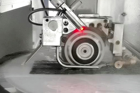
Case of turning Aircraft carbon fiber skin with PCD countersink drill

For carbon fiber skins, the rivet holes require high precision and are difficult to process, so PCD countersinking is generally used for processing.

Aircraft skin refers to the three-dimensional component that surrounds the frame structure of the aircraft and is fixed on the frame with adhesives or rivets to form the aerodynamic shape of the aircraft. The skin structure composed of aircraft skin and skeleton has a large bearing capacity and rigidity, but its own weight is very light, and it plays the role of bearing and transmitting aerodynamic loads. After the skin is subjected to aerodynamic action, the force is transmitted to the connected fuselage and wing frame. The force is complex, and the skin is in direct contact with the outside world. Therefore, not only the skin material is required to have high strength and good plasticity, but also a smooth surface. It has high corrosion resistance.

Aircraft carbon fiber skin PCD countersink drill

The key points and difficulties in the preparation of silicon carbide substrates

 Semiconductor Materials and Processes

The silicon carbide production process includes the preparation of material end substrates and epitaxy, the design and manufacture of subsequent chips, and then the packaging of devices, and finally flows to the downstream application market. Among them, the substrate material is the most challenging link in the silicon carbide industry. The silicon carbide substrate is hard and brittle, and it is very difficult to cut, grind, and polish, which makes it easier to produce waste products and reduce the yield rate during processing. At present, most international silicon carbide manufacturers are planning to change silicon carbide wafers from 6 inches to 8 inches.

Silicon carbide substrate The core material of the industrial chain, the preparation is difficult

The preparation of silicon carbide substrates mainly includes raw material synthesis, silicon carbide crystal growth, ingot processing, ingot cutting, wafer grinding, wafer polishing, and polishing pad cleaning. The link is the focus and difficulty in the entire substrate production link, and has become a bottleneck that limits the yield and production capacity of silicon carbide.

Crystal growth

Crystal growth difficulties:

Crystal growth

● Crystal growth is slow. The growth rate of silicon carbide is only 0.3-0.5mm/h, and the maximum crystal length can only reach 2-5cm, which is quite different from silicon-based substrates. And as the size of silicon carbide crystals expands, the difficulty of its growth process increases geometrically.

● The yield rate of black box operation is low. The core parameters of silicon carbide substrates include micropipe density, dislocation density, resistivity, warpage, surface roughness, etc. The production process is completely completed in a high-temperature sealed graphite cavity. It is necessary to arrange the atoms in the closed high-temperature cavity in an orderly manner to complete the crystal growth and control the parameter indicators at the same time. It is very dependent on the manufacturer's process experience and is prone to various defects and other problems. The crystal growth process is difficult, the yield rate is low, and the output is small.

● There are many types of silicon carbide crystal structures, but only a few of them are required materials. It is difficult to control impurities, and polymorphic inclusions are likely to occur, which reduces product yield.

Cutting, Grinding and Polishing

After the silicon carbide crystal is prepared, it needs to be cut into thin slices with a thickness of no more than 1mm along a certain direction, and ground with diamond abrasive fluids of different particle sizes to remove knife marks and metamorphic layers and control the thickness before CMP After polishing to achieve global planarization, it enters the final cleaning process.

Difficulties in cutting, grinding and polishing: Since silicon carbide is a brittle material with high hardness, it has serious problems such as warping and cracking during processing, and the loss is huge. Under the traditional reciprocating diamond-bonded abrasive multi-wire cutting method, the overall material The utilization rate is only 50%. After polishing and grinding, the cutting loss ratio is as high as 75%, and the usable part ratio is relatively low.

cutting ingot.jpg cylindrical grinding ingot.jpg

Slicing of SiC single crystal

As the first process in the silicon carbide single crystal processing process, the performance of the slice determines the processing level of subsequent thinning and polishing. Slicing is easy to produce cracks on the surface and sub-surface of the wafer, which increases the chip fragmentation rate and manufacturing cost. Therefore, controlling the crack damage on the surface of the wafer is of great significance to promote the development of silicon carbide device manufacturing technology.

Main Influencing Factors and Optimizing Measures of Slicing Quality

Surface crack damage is closely related to slice quality. The epitaxial growth on the silicon carbide substrate material, the device manufacturing process and the device performance are all related to the crystal orientation. In order to avoid brittle cracks in wafers caused by orientation sensitivity during slicing, crystal orientation detection is required before slicing silicon carbide ingots. Silicon carbide ingots are generally grown on the SiC { 0001} plane, and cutting along the SiC crystal plane parallel to the growth direction of the ingot can effectively reduce the through-thread dislocation density on the slice surface and improve the slice quality.

Thinning of silicon carbide wafers

2.1 The thinning of silicon carbide slices is mainly achieved by grinding and grinding.

Grinding

The most representative form of wafer grinding is self-rotation grinding. While the wafer is self-rotating, the spindle mechanism drives the grinding wheel to rotate, and at the same time the grinding wheel is fed downwards, thereby realizing the thinning process. Although self-rotating grinding can effectively improve processing efficiency, the grinding wheel is prone to passivation with the increase of processing time, the service life is short, and the wafer is prone to surface and sub-surface damage. The existence of processing defects seriously restricts the processing accuracy and efficiency. In order to solve these problems, researchers have developed different auxiliary technologies, such as online dressing of grinding wheels, or the development of new soft abrasive grinding wheels. At present, the main technologies include ultrasonic vibration assisted grinding and online grinding. Electrolytic dressing assisted grinding.

Ultrasonic assisted grinding is a method of reducing grinding force and grinding wheel wear through ultrasonic vibration, and improving processing quality. Many studies have shown that under certain process conditions, ultrasonic-assisted grinding is more suitable for thinning of hard and brittle materials than ordinary grinding.

Under the action of electrolysis during online electrolytic dressing assisted grinding, an insulating oxide film is formed on the surface of the grinding wheel, which can slow down the loss of the grinding wheel, and at the same time support a large number of electrolytically shed abrasive particles, which is similar to the grinding effect of free abrasive particles, which is conducive to improving the quality of the grinding surface.

Lapping

The lapping process can be divided into single-side and double-side grinding, and single-side and double-side grinding technologies for small-sized silicon carbide wafers have been developed one after another. When grinding the surface of silicon carbide slices, the abrasive used is usually boron carbide or diamond, which can be divided into rough grinding and fine grinding. Coarse grinding is mainly to remove the knife marks caused by slicing and the metamorphic layer caused by slicing, and the abrasive grains with larger particle sizes are used. The purpose of fine grinding is to remove the surface damage layer left by coarse grinding, improve the surface roughness, and use finer abrasive grains.


2.2 The main factors affecting the thinning effect

The study found that the wafer material removal rate in the thinning process is closely related to abrasive particle size, density, grinding disc rotation speed, grinding pressure and other factors. The higher the hardness of the abrasive grains in the slurry, the larger the grain size, and the greater the surface roughness of the processed wafer. Too hard grinding discs will damage and pollute the surface of the workpiece, soft grinding discs can allow more sliding movement of the abrasive, and the surface finish after processing is high, but the flatness is low.

Polishing of silicon carbide wafers

3.1 Research status of polishing technology

The polishing process of silicon carbide wafers can be divided into rough polishing and fine polishing. Mainly include electrochemistry, magnetorheology, plasma, photocatalysis, etc., and mechanical synergistic methods mainly include ultrasonic assistance, mixed abrasive grain and consolidated abrasive grain polishing, etc.

3.2 Key factors and development trends affecting CMP

Polishing results are optimized when the mechanical and chemical effects of CMP are balanced. The polishing effect of CMP is mainly affected by three parameters: process parameters, polishing liquid, and polishing pad. Polishing fluid and polishing pads are the main consumables in CMP, and controlling and optimizing their properties to ensure repeatable polishing efficiency is critical for process stability. Improving the polishing solution and developing a polishing pad with self-catalysis is the research direction of CMP consumables in the future.

抛光(2021.5.19).jpg

2023年3月5日星期日

Cylindrical grinding method and the choice of grinding allowance


Many shapes, sizes and types of bearings exist including: ball bearings, roller bearings, needle bearings, and tapered roller bearings

OUTER RING

The outer part of a bearing that fi ts into the housing and contains the internal raceway for the rolling elements.

INNER RING

The inner part of a bearing that fi ts on a shaft and contains the external raceway for the rolling elements.

RACEWAY

The ball or roller path, profi led in the inner and outer rings in which the balls or rollers ride. Also called: guide path, race, ball path, roller path.

EXTERNAL RACEWAY

The ball or roller path on an inner ring. Also called: inner race, inner ring race.

INTERNAL RACEWAY

The ball or roller path on the bore of the outer ring. Also called: outer ring race, outer race.

BALL

A spherical rolling element.

ROLLER

Cylindrical or conical rolling element of slightly greater length than diameter.

Cylindrical grinding and the step face.

2. The grinding method of the cylinder and the step surface

1. The method of cylindrical grinding

(1) Longitudinal grinding method

Longitudinal grinding method is the most commonly used grinding method. During grinding, the table is used for longitudinal reciprocating feed, and the grinding wheel is used for periodic transverse feed. The grinding allowance of the workpiece should be ground in multiple reciprocating trips.

bearingbearing

Characteristics of longitudinal grinding method (referred to as longitudinal method) :

1) In the whole width of the grinding wheel, the abrasive works differently. The sharp Angle of the left (or right) end face of the grinding wheel mainly plays the cutting role. Part of the grinding allowance of the workpiece is removed by the abrasive particles at the sharp Angle of the grinding wheel, while most of the abrasive particles at the width of the grinding wheel play the role of reducing the surface roughness of the workpiece. The longitudinal grinding method has low grinding force, good heat dissipation condition, and can obtain higher machining accuracy and smaller surface roughness.

2) Low labor productivity.

3) Low grinding force, suitable for grinding slender, precision or thin wall workpiece.

bearing  bearing

(2)Plunge grinding method

The length of the cylinder of the grinding workpiece shall be less than the width of the grinding wheel, and the grinding wheel shall make continuous or intermittent transverse feed movement until all the allowance is removed. There is no longitudinal feed movement of the grinding wheel. Higher cutting speed can be used in coarse grinding; In fine grinding, the cutting speed is low to prevent the workpiece from burning and heating deformation.

The characteristics of cutting in grinding method (referred to as cutting in method) :

1) The working condition of the grains on the whole width of the grinding wheel is the same, giving full play to the grinding effect of all the grains. At the same time, because of the continuous transverse feed, the basic grinding time is shortened, so the production efficiency is very high.

2) The radial grinding force is large, the workpiece is easy to produce bending deformation, generally not suitable for grinding fine workpiece.

3) Large grinding heat is generated during grinding, and the workpiece is easy to burn and heat deformation.

4) The shape of the grinding wheel surface (dressing traces) will be copied to the workpiece surface and affect the surface roughness of the workpiece. In order to eliminate the above defects, small longitudinal movement can be made at the end of the cutting method.

5) Due to the limitation of the width of the grinding wheel, the cutting method is only suitable for grinding the outer circular surface with short length.

(3) Step grinding method
Subsection grinding method is also called comprehensive grinding method. It is the comprehensive application of the cutting method and the longitudinal method, that is, the first use the cutting method to coarse grinding workpiece segments, leaving 0.03~0.04mm allowance, and finally use the longitudinal method to fine grinding to size. This grinding method not only takes advantage of the high efficiency of the cutting method, but also has the advantage of the high precision of the longitudinal method. In segmental grinding, there should be 5~10mm overlap between two adjacent sections. This grinding method is suitable for grinding the workpiece with good allowance and rigidity, and the length of the workpiece should be appropriate. Considering the grinding efficiency, wider grinding wheels should be used to reduce the number of segments. When the length of the machined surface is about 2~3 times of the width of the grinding wheel, it is the best condition.

(4) Deep grinding method
This is a more commonly used grinding method, which uses a large back bite to grind all the grinding allowance of the workpiece in a single longitudinal feed. Because the basic grinding time is shortened, the labor productivity is high.
Characteristics of deep grinding method:
1) Suitable for grinding rigid workpiece
2) Grinder should have high power and stiffness

2. Grinding method of step surface
The step surface of the workpiece can be ground out by the end face of the grinding wheel by moving the table by hand after grinding the outer circle. During grinding, the grinding wheel should be slightly removed laterally and the work table should be manually operated until the grinding wheel is in contact with the end face of the workpiece, and the grinding wheel should be fed intermittently. Pay attention to pouring sufficient cutting fluid to avoid burning the workpiece. Usually, the end face of the grinding wheel can be shaped into a concave shape to reduce the contact area between the grinding wheel and the workpiece and improve the grinding quality.
When grinding the step surface, the grinding wheel is under great lateral pressure. Therefore, it is necessary to move the table carefully during operation. When the end face of the workpiece contacts with the grinding wheel, the longitudinal feed handwheel can be gently tapped by hand to achieve small and uniform feed.

3. Selection of outer round grinding wheel
1. Principle of reasonable selection of grinding wheel
The choice of grinding wheel not only affects the machining accuracy and surface quality of the workpiece, but also affects the loss, service life, production efficiency and production cost of the grinding wheel. To achieve the purpose of reasonable selection of grinding wheel, the following basic principles should be observed:
(1) The abrasive particles shall have good grinding performance.
(2) The grinding wheel should have proper “self-sharpening” during grinding.
(3) The grinding wheel should not be blunt and has a long service life.
(4) Small grinding force is generated during grinding.
(5) Small grinding heat is generated during grinding.
(6) can achieve high machining accuracy (dimensional accuracy, shape accuracy, position accuracy).
(7) Small surface roughness can be achieved.
(8) The workpiece surface does not produce burns and cracks.

What is the sapphire window and what is it used for?


Sapphire has high hardness and is a hard and brittle material at room temperature, which is difficult to process and has a low yield. Especially in the process of precision and ultra-precision processing, sapphire sheets often have cracks, scratches, edge breakage and other defects.

sapphire windows

Sapphire material is anisotropic material, and the periodicity and density of atomic arrangement are different in different crystal direction, which leads to different mechanical properties, optical properties and electrical properties. People take advantage of this directional difference and choose products with different crystal orientation in different applications. For example, gallium nitride epitaxy usually uses C-plane, SOS usually uses R-plane, and mobile phone screen usually uses A-side sapphire wafer. In the aspect of application, the crystal direction of sapphire should be taken into account. In the process of processing, different hardness of different crystal direction can also be used to choose different processing directions, so as to improve the processing efficiency and improve the yield.

Sapphire window is a kind of parallel plane version, double plane round sapphire glass, usually used as the protection window of electronic sensors and detectors, the window piece will not change the magnification of the system, widely used in high energy detection and high power laser important window materials, such as aerospace applications.


Features of sapphire window:

Sapphire has the characteristics of high temperature resistance, good thermal conductivity, high hardness, infrared penetration, good chemical stability, good light transmission, corrosion resistance and so on.

The role of sapphire window:

Sapphire protective window is a window piece product used to protect the user or the contents of the container by using sapphire’s characteristics of pressure resistance, scratch resistance and high temperature resistance. Due to the high hardness of sapphire, it has stronger compression and scratch resistance than other glass products. Protective window pieces processed with sapphire are often used in deep water, oil fields, inflammable and explosive occasions, high pressure containers, vacuum containers and other fields.Sapphire can withstand up to 2030 degrees Celsius and is often used in high temperature containers.

In addition to its good hardness, sapphire window piece also has good electrical and dielectric characteristics, and has chemical corrosion resistance, high temperature resistance, good thermal conductivity, good chemical stability and other characteristics.So it can be used to make optical components, night vision cameras and other instruments.

The processing sequence of sapphire window pieces is usually first processed into sapphire crystal blocks, sliced before edge processing, namely chamfering and chamfering. In the process of chip or chip cutting, edge breakage is easy to occur at the edges and corners. In addition, the processing time is long because of the large amount of removal required for the edge of wafer.

The process is divided into six steps:

(I) crystal orientation

(2) Crystal square root

(3) Flat grinding chamfer

(4) Directional section

(5) Edge processing

(6) Grinding and polishing

The specific steps are as follows:

First, X-ray diffractometer is used to find planes A, C and M on the ingot surface.

The ingot is then cut into sapphire hexahedra.

The surface of the sapphire crystal block was smoothed with A grinder, and the 4 edges perpendicular to the A-side were pre-chamfered.

Use A multi-line cutter to cut the sapphire blocks into A – directional wafers.

The edge of the wafer is chamfered with an engraving or chamfering machine.

The wafer is processed into the final product by means of mechanical grinding and chemical mechanical polishing.

Diamond grinding wheel is the most widely used in the processing of sapphire silicon wafer and other hard and brittle materials. Different kinds of diamond grinding wheels are used in the processing of crystal rod, rough machining of wafer and then fine machining. They are respectively crystal rod roller grinding wheel and face grinding wheel The diamond size ranges from 100# to 8000#. The matrix materials include metal bond, resin bond and ceramic bond.

electroplated diamond band sawCylindrical Grinding wheel back gring wheel

Edge Grinding Wheel, dicing blade polishing PAD

A large number of diamond grinding wheels are also used in sapphire processing, for example, the outer diameter grinding crystallization flattening, mainly using resin bonded diamond grinding wheels, coarse grinding particle size of about 100#, about 200# fine grinding, resin bond has a certain elasticity, play a polishing role, the processed workpiece quality is good.

Chamfered edging grinding wheel is metal bonded diamond grinding wheel, common size :1FF1V/9 202*20*30*2.5, metal bonding has higher toughness and strength, high groove precision, long service life, sapphire window rough grinding using ceramic diamond grinding disc processing, compared with cast iron disc processing, has high processing efficiency, high precision, Good grinding quality, long service life and so on. In addition, backside thinning grinding wheel, diamond abrasive liquid and other products are also widely used, which have great market value.


Application hybrid CBN grinding wheel for medical stainless cutting tools


New requirements for precision tools in the medical industry
Difficult-to-machine materials, complex workpiece shapes and frequent small-batch production place high demands on the tools used to process medical materials. The precision tools produced by Walter enjoy a high reputation in this field.
Medical materials, such as implant products and prosthetics, play an important role in successful surgical procedures, helping surgeons achieve optimal medical outcomes. Cutting tools for processing medical materials determine the quality of medical materials to a large extent. The use of cutting tools in the manufacture of medical materials is diverse and extensive. It can process relatively simple workpieces such as large-scale equipment (such as computerized tomography cameras), while the production of implanted products or workpieces used to repair the skull or treat fractures. more challenging.

Precision – the most basic requirement
Tolerances in the micron range are common in the medical industry, and selecting the correct tool requires insight and experience. On the one hand, even drilling small holes requires the use of lubricants to reduce friction, reliably dissipate heat and dispose of fine iron filings at the cutting edge; cutting tools for high-quality surfaces. Commonly used cutting tools are high-speed steel drills or solid carbide drills. Walter Titex (Walter Titex) drill bit of Walter Group in Germany is used for processing difficult-to-machine materials such as titanium, stainless steel, precious metals and even composite materials. The diameter of the drill bit can reach 0.75mm.
Milling and Drilling – Dental Restoration
In the material selection of orthopedic cutting tools , stainless steel cutting tools occupy a large part. The grinding problem of stainless steel cutting tools is placed in front of the processor. The slotting of the cutting tools is the process with the largest machining allowance and the most time-consuming. For this application, we have developed a grinding wheel specially for stainless steel tool grooving, and conducted a series of experimental tests. The specific test results are as follows:

3A1


Test purposeTest hybrid CBN grinding wheel for fluting stainless cutting tools
Test equipmentDjtolS500   Spindle power:6KW
Size of grinding wheel3A1 100X31.75X10X3
Grinding wheel formulaB107 hybrid-A
Workpiece material30Cr13 stainless,Heat treatment hardness-52
Workpiece parametersDiameter4mm,4×27,twirl angle-40°rake-5°
Grinding processlinear velocity:30m/s

cutting depth:0.6mm+0.5mm

The cutting speed setting value is 600, and the grinding wheel is not sharpened

Grinding effectSharpness: the grinding power is about 150 watts after the grinding is stable

Durability: 70 pieces of bar (equivalent to the machining allowance of 200 pieces of cutting tools from the customer) after slotting, measure the radius of the grinding wheel from R0.05mm to R0.10mm

Welcome to visit our website to know more

Email: info@moresuperhard.com
WhatsApp:+8618239888691


2022年11月25日星期五

What is the hardness of grinding wheel?

 What is the hardness of grinding wheel?

diamond powder

The hardness of grinding wheel refers to the adhesive strength of the bond to the abrasive(how easy it is for the abrasive to detach from the grinding wheel). The hardness of the grinding wheel is determined by the bonding strength of the binder, not by the hardness of the abrasive. Under the same conditions and certain external force, if the abrasive particles are very easy to fall off from the grinding wheel, the hardness of the grinding wheel will be relatively low (or soft). On the contrary, the hardness of the grinding wheel is relatively high (or hard).

What is self-sharpening of grinding wheel?

CNC tool grinding.png

After the abrasive particles on the grinding wheel are passivated, the grinding force acting on the abrasive particles increases, which makes the surface abrasive particles of the grinding wheel fall off automatically, and the sharp cutting edge of the new abrasive particles in the inner layer is put into cutting, and the grinding wheel recovers its original cutting performance. This ability of grinding wheel is called "self-sharpening".

Whether the grinding wheel hardness is reasonable or not has great influence on the grinding quality and productivity. Generally speaking, the harder the component material, the softer the grinding wheel should be. This is because the hardness of the parts is high and the abrasive wear is fast. Choosing a softer grinding wheel is conducive to the "self-sharpening" of the grinding wheel. However, if the hardness is too low, the grinding wheel will wear quickly and it is difficult to ensure the correct sand profile. If the hardness of the grinding wheel is too high, it is difficult to realize the self-sharpening of the grinding wheel, which is not only low productivity, but also easy to produce high temperature burns on the surface of parts.

If the grinding wheel is soft, it is easy to dressing, but the retention of shape and contour is usually not ideal. In order to improve the surface roughness of the workpiece, the hardness of the grinding wheel is too high will occur heat and shake, resulting in the problem of poor surface roughness.

  Importance of cutting force

PCD tool grinding.png

If the forming wheel to maintain the force, the best way is increasing the hardness of the wheel. However, it is easy to occur the problem of cutting force, if the grinding wheel cutting force is good, grinding resistance is small, in addition to the speed of feeding can be accelerated, the heat will be less, the grinding wheel cooling and heat change degree is small, the grinding wheel consumption will be less. If only hardness is required, the grinding temperature may rise even higher and the grinding wheel consumption may even speed up.

Enhancement of bond

The choice of abrasive particle size is mainly related to the surface roughness and productivity.

Bond is the key to the self-sharpening of grinding wheel and the main determinant of the hardness of grinding wheel.
In terms of forming grinding, the requirements of bond, in addition to balance cutting force and shape holding force, if the heat dissipation and grinding ratio can be further improved, the grinding efficiency will be greatly improved.
In addition to the significant improvement of the grinding ratio, the reduced binder also means that the space of the pores is made available, the space for heat dissipation is increased and the chance of blockage is reduced.


Bond

Characteristics

Ceramic bond

Good chemical stability, heat resistance, corrosion resistance, cheap, accounting for 90%, but brittle, should not be made into thin sections, should not be high-speed, linear speed is generally 35m/s

Resin bond

High strength, good elasticity, impact resistance, suitable for high-speed grinding or cutting grooves and other work, but poor corrosion resistance and heat resistance (300℃), good self-sharpening.

Metal bond

Bronze, nickel, etc., high strength and toughness, good formability, but poor self-sharpening, suitable for diamond, cubic borax nitride wheel.

Coarse grinding

During coarse grinding, the grinding allowance is large, the required surface roughness value is large, should choose a coarser abrasive. Because of coarse abrasive particles, large pores and large grinding depth, the grinding wheel is not easy to block and heat.

grinding wheel

Fine grinding

In fine grinding, the allowance is small and the required roughness value is low, so fine grinding particles can be selected. Generally speaking, the finer the abrasive particles, the better the grinding surface roughness. Granularity is not the only factor that plays a decisive role. I have seen mirrors made with 80K grinding wheels. See Table 3 for the application of grinding wheels with different grain sizes.

Not "hard" is suitable
In the selection of forming grinding wheel, the most important thing is to avoid the blind spot of grinding wheel hardness. In fact, more attention should be paid to the basic performance of grinding wheel such as cutting force, organization uniformity and heat dissipation, so as to select the most suitable product.

The hardness of grinding wheel:

Hardness

Workpiece

Grinding wheel

HRC<45

M

HRC<45-55

L

HRC<50-60

K

HRC<58-62

J

HRC<60-65

H

https://www.moresuperhard.com/Blogs/641.html

How to ultra dicing wafer with diamond dicing blade?

  afers are the basic raw materials for the production of semiconductor devices. High-purity semiconductor materials are made into wafers th...