Working principle of centerless grinding
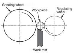
The grinding wheel rotates at a high speed, while the regulating wheel rotates in the same direction at a slow speed, thus driving the workpiece to rotate and make circular feed. The axial feed can be realized by adjusting the inclination Angle of the regulating wheel axis during through-grinding, and the radial feed can be realized by moving the regulating wheel frame or grinding wheel frame during entry grinding.
In centerless grinding, the center of the workpiece must be higher than the center line of the grinding wheel and the regulating wheel, so that the contact point between the workpiece and the grinding wheel and the regulating wheel is impossible to be symmetric, so that some convex surfaces on the workpiece can be gradually rounded in multiple rotation. If the top surface of the bracket is horizontal, and the center of the adjusted piece is at the same height with the center of the grinding wheel and the regulating wheel, when there is a raised point on the workpiece and the regulating wheel contact, the opposite side of the raised point is ground into a pit, and its depth is not affected by the height of the raised point. After the workpiece turns 180 degrees, the raised point contacts with the grinding wheel. At this time, the pit is just at the Angle of contact with the regulating wheel, and the raised point cannot be ground flat. At this time, the outer circular surface of the workpiece is an edge circle with the same diameter.
The grinding wheel, regulating wheel, and workpiece actually rotate in the same direction at different speeds.
The grinding wheel rotates at high speed, and the linear speed of the grinding wheel is very high, generally around 35m/s
The slow rotation of the regulating wheel plays a guiding drive role. The linear speed of the regulating wheel is 10-50m /min. The speed of the regulating wheel determines the rotation speed of the workpiece, and the linear speed of the workpiece is basically equal to that of the regulating wheel.
In order to avoid grinding out the rounded workpiece, the center of the workpiece must be higher than the center line between the grinding wheel and the regulating wheel (higher than 15% ~ 25% of the workpiece diameter), so that the contact point between the workpiece and the grinding wheel and the regulating wheel is not on the same diameter line, so that the workpiece can be gradually rounded during multiple rotation.
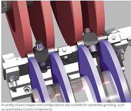
Centerless grinding is suitable for grinding slender shaft and shaft, sleeve, pin and other small parts without center hole in mass production. In fact, no grinding application industry is very wide:
- Aerospace
- Agriculture
- Automotive
- Defense
- Medical
- Military
- Motorsport
- Power generation
- Research and development
- Sub-sea oil and gas
-White goods
Centerless grinding grinding method
Infeed grinding/plunge grinding
The supporting plate is equipped with axial positioning fulcrum, and the workpiece is supported at a certain position on the supporting plate, and grinding is carried out by grinding wheel or regulating wheel. It is used for grinding workpiece with shaft shoulder or boss as well as cone, sphere or other rotating body workpiece.
Thru-feed grinding
The workpiece is fed along the axis of the grinding wheel for grinding, and the small dip Angle of the regulating wheel axis is adjusted to realize the axial feed of the workpiece. It is suitable for grinding thin cylindrical workpiece, short shaft and sleeve workpiece without center hole.
Thru-feed and Infeed grinding
Thru-feed and Infeed grinding is a combination of the above two kinds. In addition, there are tangent feed grinding and step workpiece in the axial forward and backward face feed grinding.
The maximum machining diameter of centerless grinding is 500, which is quite unexpected. The previous found that the diameter of the products that can be grinded by centerless grinding ranges from 1.2mm to 300mm. It is rare to see such a large diameter of 500. With the development of grinder and market demand, it should not be a problem.

Many of the common types of grinding wheels used for centerless cylindrical grinding machines in China have been replaced by resin and ceramic superhard diamond wheels. The most common specifications for resin and ceramic centerless grinding wheels:
D250-T125-H75-X10
D300*T50/T100*H127-X10
D350-T100/T125-H127-X10
D400-T100/T150-H203-X10
D500-T150-H305-X10
D600-T200-H305-X10
The following are common centerless grinding wheel sizes
1. Resin centerless grinding wheel
Diameter(mm) | Diamond layer(mm) | |
300 | 50 |
5,10 |
100 | ||
150 | ||
350 | 100 | |
125 | ||
150 | ||
400 | 100 | |
150 | ||
205 | ||
450 | 100 | |
150 | ||
205 | ||
500 | 150 | |
200 | ||
250 |
2.Abrasive selection
A: Grinding of ordinary carbon steel bearings and bearing inner and outer rings
WA: Precision grinding of alloy steel bearings and bearing inner and outer rings
GC: Micro motor shaft grinding
A/WA: Grinding of bearing steel, bearing raceway and inner hole
Particle size to choose
According to the different machining roughness requirements, the size selection range is generally 60#-180#
Hardness to choose
J. K. L. M. N
Linear velocity standard
The working line speed of centerless grinding wheel is 35M/S. The order of 60M/S high speed grinding wheel is also accepted.
Grinding machine type | Grinding wheel size (mm) |
M1020 | P300*100*127 |
AMG1020 | PSA300*100*127 |
MT1040 | PSA350*125*127 |
AM1050 | P400*150*203 |
AMG1050 | P500*150*305 |
AM1080 | P600*200*305 |
MGT1050 | P450*150*250 |
C-12 | PSA305*150*120 |
C-18 | PSA455*205*228.6 |
C-18A | PSA455*255*228.6 |
C-18B | PSA455*305*228.6 |
C-20 | PSA510*205*254 |


没有评论:
发表评论